
Why Tolerances Can’t Be Zero
There’s a certain satisfaction when things line up just right. When something runs like clockwork, or fits like a glove. Without discrete units of measurement, it’s easy to assume a perfect fit.
Dive into manufacturing and it’s a world of numbers. Tape measures, calipers, micrometers. In the metal hose industry, working with sheet metal, strip material is measured in thousandths of an inch. Assembly drawings mark overall length to a similar degree. No longer just a “feel,” fit now has defined measurements.
Once we know precisely what something is, we also know precisely what it is not. Stainless steel strip that is .018” thick is incredibly thin, but not as thin as strip that is .010” thick. To many the difference may not be noticeable. To others–and to our machines–it’s all too apparent.
But just how strictly must requested dimensions be matched?
Tolerance: Range of Acceptability
While our thickest strip (.035”) will not run in machines designed to make hose using our thinnest strip (.006”), and vice versa, each machine does have a (smaller) range of acceptable thicknesses. We refer to these ranges as tolerances.
For our thinnest strip, tolerance is +/- .00030” meaning the machine can run strip so long as it falls within this defined range on either side of .006”. From measuring the thickness of strip to the length of an assembly, measurements are taken throughout the manufacturing process to ensure dimensions fall within predetermined tolerances.
Why Tolerances are Important in Fluid Conveyance
Since metal hose assemblies are connected into an existing piping system or attached to a piece of equipment parameters are needed to ensure the component fits with what is already there.
Industry association NAHAD has published guidelines on assembly overall length tolerances. This is considered the standard.
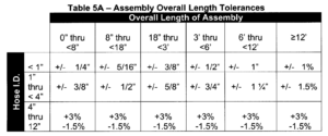
In the drawing below, this 1½” assembly has an overall length (OAL) of 24”. In line with the NAHAD guidelines, the tolerance is +/- ⅝.” The hose will fit into its chosen application so long as its OAL ranges from 23⅜” – 24⅝”.

Setting Realistic Expectations
Since the allowances of our manufacturing processes are so small, we understand the need for close tolerances. However, it is important to set realistic expectations for metal hose.
The unique flexing characteristics of metal hose limit how tight tolerance can be. For one, when the hose is prepped for an assembly, it is cut in the valley of a corrugation. Compared to a straight tube where a 1-foot piece will match another 1-foot piece, a 1-foot section of corrugated hose may not exactly match another 1-foot section because of this requirement for a valley cut.
An exact 1-foot measurement may stop and start along the sidewalls, crests or valleys of corrugations at each end. There’s no guarantee that the corrugation valleys will align exactly with the designed measurement. This can sometimes be corrected by adjusting the length of the fitting, but some fittings, such as flanges, are not modifiable.
For another, a hose’s ability to flex means it likely will not return to the exact same length once bent. Storing, testing and shipping can all change the length of a hose after it is made. This can be a point of frustration to the perfectionist, but it’s important to note too that hoses typically elongate once pressurized.
The geometric properties that allow metal hoses to absorb movement also mean an assembly’s length does not remain exactly the same throughout its life. It is now easier to see why tolerances cannot be zero.
Designing to Account for Tolerances
As metal hose typically has larger tolerances compared to machined parts, it is not always suited for critically tight applications. When designing a system for the first time, it is ideal to have some redundant length so that the assembly is not always on the limit of recommended use. This is applicable to loops, where the added length will create a larger bend radius and help increase the cycle life of the assembly. For straight lengths, hoses should be kept on the shorter side to limit the effect of loose braid in fabrication or be built in such a way that there is some axial give to allow the hose to elongate.
When replacing hoses in low tolerance, straight configurations, hoses should be built slightly shorter. A shorter hose can be tightened into place, whereas if a longer hose is compressed to fit a tight space, failure is likely. Of course, this type of configuration should be avoided if possible and alternatives such as expansion joints should be considered.
Systems that use metal hose must be designed to account for the inherent tolerance associated with metal hose assemblies. Tools on our website can help find the minimum length for certain applications. However, engineers are always standing by to assist.
