Archive

Author Archive

Operating Conditions and Reduction Factors Consideration

Note: To print, please click here

When selecting a hose for a specific pressure application among various factors that must be taken into consideration, the operating temperature and dynamic stress (pressure spikes, vibration, frequent movements etc.) are the most important parameters to consider. The working pressures published in Penflex’s product catalog apply to operating conditions at 70°F and therefore at higher operating temperature, they  need to be reduced by applying temperature adjustment factor.

Because braid is the main component of the assembly that prevents the hose from elongation due to internal pressure, temperature adjustment factors should be based on the alloy used in the braid wire and are listed in the table below.

Temperature Adjustment Factor (based on braid alloy)

Temp. °F 304/304L
Stainless
Steel
316L
Stainless
Steel
321
Stainless
Steel
Carbon Steel Monel Bronze
70 1.00 1.00 1.00 1.00 1.00 1.00
150 .95 .93 .97 .99 .93 .92
200 .91 .89 .94 .97 .90 .89
250 .88 .86 .92 .96 .87 .86
300 .85 .83 .88 .93 .83 .83
350 .81 .81 .86 .91 .82 .81
400 .78 .78 .83 .87 .79 .78
450 .77 .78 .81 .86 .77 .75
500 .77 .77 .78 .81 .73
600 .76 .76 .77 .74 .72
700 .74 .76 .76 .66 .71
800 .73 .75 .68 .52 .70
900 .68 .74 .62
1,000 .68 .74 .62
1,100 .58 .67 .58
1,200 .53 .61 .53
1,300 .44 .55 .46
1,400 .35 .48 .42
1,500 .26 .39 .37

For example to calculate the Maximum Allowable Working Pressure (MAWP) for 3/4″ ID, 321 Stainless Steel Corrugated hose single-braided with 304L braid, which will be used at operating temperature of 800°F, the following calculations should be performed:

MAWP = Working Pressure at 70°F x Temp. Adjustment Factor = 792 PSI x 0.73 = 578 PSI

If the assembly will be subjected to dynamic stress such as fluctuations in pressure, then additional reduction factors should be applied to calculate MAWP. Some reduction factors for common pressure fluctuations (designated by NAHAD) are listed in the table below:

Pressure Fluctuation Derating Factor
Normal 1.00
Pulsating 0.50
Spike 0.17

So, if our assembly (from the example above) will be subjected not only to high temperature environment, but also will be experiencing pulsating pressure fluctuations, then MAWP has to be reduced even further:

MAWP = 792 PSI x 0.73 = 578 PSI x 0.50 = 289 PSI

To print, please click here

Calculation of Pressure Loss in Corrugated Hoses

When designing piping systems, it’s important to consider pressure loss, or drop, through the hose. This will allow you to assess its impact on the piping system’s operation.

It’s a difficult calculation—being based on flow rate (volume per time)—and one that depends on several variables including the type of media passing through the hose, the geometry of the hose and the application setup. The only way to truly determine pressure drop in a hose is to set a gauge at one end and another at the other, and to then take a reading.

However, if accurate readings of inlet and outlet pressure are not readily available, we can roughly estimate pressure drop in a corrugated hose based on what we would see in steel pipe under similar flow conditions. Due to its profile, pressure loss in corrugated hose is significantly higher than that in steel pipes. As a general rule, pressure drop in the turbulence zone of corrugated hose will be 150% higher than in steel pipe while pressure drop in the high velocity zone will be 450% higher.

Pressure Loss Scenario

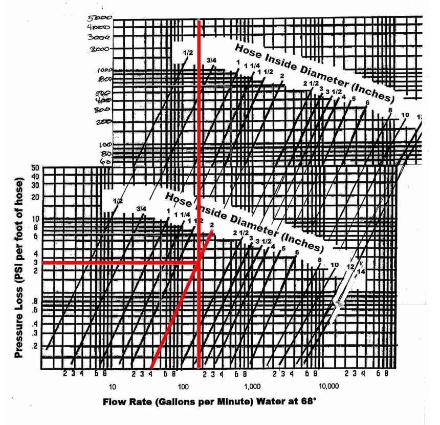
For example, let’s say we need to calculate the pressure loss in 2” (ID) corrugated hoses that are 85 feet long and transferring water with flow rate of 1400 cubic feet per hour.

By using Penflex’s Pressure Loss calculator we find that 1400 ft3/hour corresponds to 175 gal/min.

To convert flow rate from Cubic Feet per Hour to Gallons per Minute, use the calculator below:

Then we plot the 175 gal/min on the X-axis of this chart until we “hit” the line for 2″ hose ID, then by going over horizontally to the Y-axis, we find that pressure loss per foot of hose will be about 3.7 psi.

Thus, the total pressure drop over the hose length will be 314.5 psi (3.7 psi x 85 feet).

Keep in mind that if you transfer gaseous substance through the hose then you need to find the ratio of the density of gas over the density of water and adjust the pressure drop respectively.

For example if you transfer natural gas (density = 0.050 lb/ft3) and knowing that water density is 62.4 lb/ft3 we can find out the pressure drop as the following: 3.7 psi x (0.050/62.4) = 0.0030 psi/ft or 0.255 psi for entire length of hose (85 x 0.003).

For calculations relevant to your application, you can download and print a blank chart.

Please contact us with any questions.

Corrugated Metal Hose in Externally Pressurized System Under Vacuum

Note: To print this bulletin on corrugated metal hose, please click here

When a corrugated metal hose is considered for use in a system which is externally pressurized or under vacuum conditions, as the case may be with vacuum pumps,  the question as to how the hose will behave under “full vacuum” or “perfect vacuum” is often asked.

The definition of vacuum is used to describe any pressure that is lower than standard atmospheric pressure. The most widely accepted unit of vacuum measurement is the Torr (after an Italian scientist Torricelli). So one standard atmospheric pressure can be expressed, in the units more commonly used within our community, as the following:

1 atmosphere = 760 Torr = 14.7 PSI

According to Columbia Encyclopedia, “a perfect vacuum has never been obtained,” and therefore expressions “full vacuum” or “perfect vacuum” are used loosely to express conditions with near “0” pressure.

Take a look at the table below to compare different “vacuum conditions.”

Pressure
(Torr)
Pressure
(PSI)
Vacuum Cleaner 600 11.60
Liquid Ring Vacuum Pump 24 0.46
Rotary Vane Pump 1 to 0.01 0.02 to 0.0002
Near Earth Outer Space 0.00001 0.000000002

As to the above mentioned question the answer is corrugated metal hose can be used under vacuum conditions and will not be overstressed under such condition, provided the hose section is adequately braced against buckling. The design approach is similar to that for internally pressurized system keeping in mind that external air pressure causes the hose to contract inwardly rather than expand axially. The proper design though, requires evaluation of the system as a whole not just one segment – such as corrugated hose – at a time.

If you have any questions or comments, please contact us.

To print, please click here

Calculating Pitting Resistance Equivalent Number (PREN)

Note: To print this bulletin on calculating pitting resistance equivalent number (PREN), please click here

When a metal hose is considered in an application for transferring an aggressive media, like high chlorides, or when it fails while in service due to pitting corrosion or chloride stress corrosion cracking, it is essential to use a hose or replacement hose manufactured from the proper alloy to prevent future failure. Many times a failed hose is replaced with the same alloy and most likely will fail within the same time frame.

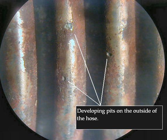
Stress corrosion cracking usually starts with pitting corrosion. The most common cause of pitting in stainless steel is acid chlorides. Chlorides react with chromium to form the very soluble chromium chloride (CrCl3), removing chromium from the passive layer, and leaving only the active iron. As the chromium dissolves, chlorides bore into the surface of stainless steel creating spherical, smooth wall pits which become stress concentrators.

To improve the pitting corrosion resistance of stainless steel such alloying elements like molybdenum (Mo) and/or nitrogen (N) are added. To help in the selection of an appropriate alloy for an application an equation called the pitting resistance equivalent number, or PREN, has been developed. PREN is a theoretical way of comparing the pitting corrosion resistance of various types of stainless steels based on the chemical compositions of an alloy.

The most commonly used formula is as follows:

PREN = %Cr + 3.3(%Mo) + 16(%N)

The table below shows a comparison range of calculated PREN values for common alloys. The higher PREN for an alloy the better its resistance to pitting corrosion.

Alloy PREN
304, 304L, 309, 310, 321 18.0 – 20.0
316, 316L 22.6 – 27.9
317, 317L 27.9 – 33.2
AL-6XN 39.8 – 45.1
Inconel® alloy 625 46.4 – 56.0
Hastelloy® alloy C-276 64.0 – 73.8

Note: A PREN of 32 is considered the minimum for seawater pitting resistance.

If you have any questions or comments, please contact us.

Disclaimer: The info presented here has been compiled from sources believed to be reliable. No guarantee is implied or expressly stated here and the data given is intended as a guide only.

To print, please click here

Corrugated Metal Hose and Flow Velocity Consideration

Note: To print this bulletin on corrugated metal hose and flow velocity consideration, please click here

The flow velocity in corrugated metal hose should never exceed 150 ft./sec. for gas or 75 ft./sec. for liquids otherwise a resonant vibration can occur. Resonant vibration may cause very rapid failure of the assembly.

To figure out maximum allowable flow rate for Penflex 700 and P5 Series hoses, please refer to the table below:

Maximum Permissible Flow Rates

GAS LIQUID
Product
ID
Hose
ID (in.)
CFH
( ft3/hour)
CFM
( ft3/min.)
CFH
(ft3/hour)
CFM
( ft3/min.)
7xx-004 1/4″ 283 4.72 141.5 2.36
7xx-006 3/8″ 544.4 9.08 272.2 4.54
7xx-008 1/2″ 923.4 15.4 461.7 7.7
7xx-012 3/4″ 1,882.7 31.4 941.4 15.7
7xx-016 1″ 3,309.8 55.2 1,654.9 27.6
7xx-020 1-1/4″ 5,156.6 86 2,578.3 43
7xx-024 1-1/2″ 8,034.6 134 4,017.3 67
7xx-032 2″ 11,770.1 196.3 5,885.1 98.15
7xx-048 3″ 26,482.5 441.67 13,241.3 220.835
7xx-064 4″ 47,068.6 785 23,534.3 392.5
7xx-080 5″ 72,911.4 1,216 36,455.7 608
7xx-096 6″ 104,930 1,750 52,465 875
7xx-128 8″ 179,880 3,000 89,940 1,500
7xx-160 10″ 275,816 4,600 137,908 2,300
7xx-192 12″ 407,728 6,800 203,864 3,400
7xx-224 14″ 509,660 8,500 254,830 4,250
7xx-256 16″ 689,540 11,500 344,770 5,750
7xx-288 18″ 869,420 14,500 434,710 7,250
7xx-320 20″ 1,079,280 18,000 539,640 9,000
7xx-352 22″ 1,319,120 22,000 659,560 11,000
7xx-384 24″ 1,588,940 26,500 794,470 13,250

Where the flow velocity exceeds these rates, an interlocked metal hose liner or larger hose I.D. is recommended. We dive deeper into this topic here.

If you have any questions or comments, please contact us.

To print, please click here

Assembly Installation Handling Precautions

Note: To print, please click here

Penflex corrugated hose is engineered to provide maximum service life when properly installed. Improper assembly installation, incorrect flexing or careless handling in an application will reduce the effective service life of the hose and cause premature failure of an assembly. The following assembly installation and handling precautions should be observed to achieve optimum performance from your corrugated hose assemblies.

  • Avoid torque.
    Do not twist the hose assembly during installation when aligning the bolt holes in a flange or in making up pipe threads. The utilization of lap joint flanges or pipe unions will minimize this condition. It is recommended that two wrenches be used in making the union connection; one to prevent the hose from twisting and the other to tighten the coupling.
  • In plane lateral offset installation.
    Prevent out-of-plane flexing in an installation. Always install the hose so that the flexing takes place in only one plane. This plane must be the plane in which the bending occurs.
  • Avoid over bending.
    The repetitive bending of a hose to a radius smaller than the radius listed in the specification tables for corrugated hose will result in premature hose failure. Always provide sufficient length to prevent over bending and to eliminate strain on the hose.
  • Avoid sharp bends.
    Utilize sound geometric configurations that avoid sharp bends, especially near the end fittings of the assembly.
  • Provide support.
    When installing the assembly in a horizontal loop, provide support for the arms to prevent the hose from sagging.
  • Do not extend or compress axially.
    A piping system which utilizes metal hose to absorb movement must be properly anchored and/or guided. Always support the piping to prevent excessive weight from compressing the hose and relaxing the braid tension.
  • Handle with care.
    Avoid careless handling of the hose assembly. Always lift or carry metal hose to prevent abrasion damage particularly to braided corrugated hose. Store metal hose assemblies away from areas where it can be subjected to spillage, corrosive fumes or sprays, weld splatter, etc.

If you have any questions or comments, please contact us.

To print, please click here

Service Temperatures of Austenitic Steels & Other Materials

Note: To print, please click here.

Most common reasons for using stainless steels are their corrosion resistance and their high temperature properties. Therefore stainless steels can be found in applications where high temperature oxidation resistance is necessary and in applications where high temperature strength is required. The high chromium content which is so beneficial to the wet corrosion resistance of stainless steels is also highly beneficial to their high temperature strength.

Most austenitic steels, with chromium contents of at least 18%, can be used at temperatures up to 1500°F and Grade 310 (Cr content: up to 26%) even higher – up to 2000°F. Because of the problem of grain boundary carbide precipitation, discussed in Engineering Bulletin #103, prolonged exposure to the temperature in the 1100°F to 1400°F range should be avoided.

The table below shows the (approximate) maximum service temperatures of austenitic steels & other common materials.

Maximum Service Temperatures of Austenitic Steels & Other Common Materials in Dry Air

Alloy Temperature
°F °C
Inconel 600 2150 1175
310 2100 1150
Inconel 625 1800 982
Hastelloy C276 800 427
304/304L 1500* 816
321 1500* 816
316L 1500* 816
AL6XN 1000 538
Monel 400 800 427
Bronze 450 232
Brass 450 232
Copper 400 204

Note: the temperature ratings in the table are general guidelines and could change if corrosives are present, such as sulfur, carbon, etc. In some cases ASME codes will reduce temperature limits too.

*For applications where temperatures exceed 1000°F, read about H Grade alloys in Bulletin #137 or contact us.

Disclaimer: The info presented here has been compiled from sources believed to be reliable. No guarantee is implied or expressly stated here and the data given is intended as a guide only.

To print, please click here.

Chloride/Chlorine Levels and Stainless Steel Alloy Selection

Note: To print this bulletin on chloride/chlorine levels and stainless steel alloy selection, please click here

Pitting Corrosion on Stainless Steel Hose

Pitting corrosion occurs when chloride levels exceed recommended levels.

The 304 and 304L (18-8 stainless steel alloys) have been utilized very successfully in fresh waters containing low levels of chloride ion of up to 100 ppm. This level of chloride is considered to be the limit for the 18-8 alloys, particularly if crevices are present. Higher levels of chloride might cause crevice corrosion and pitting. The 18-8 alloys are not recommended for exposure to marine environments which have much higher levels of chloride.

The resistance of the stabilized Alloys 321 to pitting and crevice corrosion in the presence of chloride ion is similar to that of Alloy 304 or 304L stainless steels because of similar chromium content. And therefore 100 ppm chloride in aqueous environments is considered to be the limit for the stabilized alloys, particularly if crevices are present.

For more severe conditions of higher chloride level, lower pH and/or higher temperatures, alloys with Mo (molybdenum), such as Alloy 316, should be considered. The Mo-bearing Alloy 316 and Alloy 316L may handle waters with up to about 2000 ppm of chloride.

Another factor to consider is the amount of free Chlorine (Cl2) (usually derived from sodium hypochlorite) which is added to water (well water, drinking water, swimming pool water, etc.) to kill bacteria. Cl2 (chlorine) is a very potent oxidizer (reason it kills bacteria) and therefore high levels of Chlorine may accelerate chloride corrosion of stainless steels. 304 and 304L, 321 SS may be used for “water applications” with up to 2 ppm chlorine, while 316 and 316L alloys may “take” up to 4 ppm.

If looking for information about Chlorine Transfer Hoses, please click here.

If you have any questions or comments, please contact us.

Disclaimer: The info presented here has been compiled from sources believed to be reliable. No guarantee is implied or expressly stated here and the data given is intended as a guide only.

To print, please click here

The Advantages of Using Monel Hose vs. Teflon for Chlorine Transfer

The Chlorine Institute’s Pamphlet 6 “Piping Systems for dry chlorine” provides useful information and gives practical suggestions for the selection of material suited for chlorine piping systems. Materials of construction for chlorine transfer hoses are discussed in Appendix A of the Pamphlet. It is permitted for chlorine transfer hoses to have both metallic and non-metallic inner cores. In case of metallic hose the inner core shall be Monel 400 (UNS N04400) or Hastelloy C-276 (UNS N10276). For non-metallic hoses the inner core shall be virgin, unfilled PTFE with or without fiberglass reinforcement. So, what are the advantages and disadvantages of one material over the other?

The issue of permeability is probably the most commonly cited disadvantage for non-metallic hoses. Though certain technological advances have been made to reduce permeability in PTFE, the issue is still addressed directly in Section 7.5 of Appendix A, which states:

“Permeability: The inner core of non-metallic hoses is subject to some degree of permeability of chlorine. The braid and chafe guard shall be designed to allow chlorine which permeates the inner core to escape to atmosphere. Uses of non-metallic hose shall be limited to applications where adequate ventilation has been provided.”

Non-metallic hoses would appear to have other “limiting” characteristics as well. Although chlorine transfer hoses are only required to be designed for temperatures between -40F and 122F (which PTFE hoses can certainly handle), Monel hoses can operate from -300F to 800F. Finally, Positive Material Identification (PMI) can be used to confirm that metallic hoses are constructed from specific alloys. There is no known PMI for non-metallic materials.

Penflex designs and manufacturers Monel and Hastelloy Chlorine Transfer Hoses in complete compliance with The Chlorine Institute’s Pamphlet 6. To learn more about them, click here.

If you have any questions or comments, please contact us.

The Advantages of Using 321 SS vs. 304/304L SS

Note: To print this bulletin on the advantages of using 321 SS vs 304/304L SS, please click here

At first glance, it appears that type 304/304L SS is very similar to type 321 SS. When comparing the chemical composition of 321 SS and 304/304L SS, it is clear that the chromium (Cr) and nickel (Ni) ranges of these alloys are very similar. The difference appears when the issue of carbide precipitation in the heat-affected zone (HAZ) is discussed or fatigue strength and temperature are considered.

Carbide precipitation

The weld areas with temperatures 930°F – 1470°F are often called the carbide precipitation zone – in which Chromium (Cr) combines with Carbon (C) and precipitates chromium carbides at the grain boundaries significantly reducing corrosion resistance of steel in this zone. One of the ways to combat this phenomenon is to lower the carbon content in steel to decrease the carbide precipitation. 304L SS is an example of such steel; the “L” in 304L is for “Lower carbon” (.030% max vs. .080% max for 304 steel). An even more effective way to reduce carbide precipitation is through the addition of Titanium (Ti) to the alloy to stabilize it. The carbon is more attracted to the Titanium (Ti) and therefore it leaves the chromium alone. To be a true “stabilized” grade the 321 steel has to have Titanium (Ti) content at least 5 times than its Carbon (C) content. Reduced risk of corrosion in the HAZ is the main advantage of 321.

Fatigue strength

In dynamic applications, fatigue strength is also important to consider. And in this respect 321 SS has a slight advantage over 304 SS. Fatigue or endurance limits (strength in bending) of austenitic stainless steels in the annealed condition are about one-half the tensile strength.Typical tensile and endurance limits for these alloys (annealed) are presented in the table below:

Alloy Typical Tensile Typical Endurance Limit
304L 68 ksi 34 ksi
304 70 ksi 35 ksi
321 76 ksi 38 ksi

Temperature Factors

Temperature factors could be another factor to consider in some applications. As we can see in the table below the temperature reduction factors are slightly higher for 321 than for 304L at most elevated temperatures:

TEMP ° F 304L FACTOR 321 FACTOR
70 1.00 1.00
150 0.95 0.97
200 0.91 0.95
250 0.88 0.93
300 0.85 0.91
350 0.81 0.89
400 0.78 0.87
450 0.77 0.85
500 0.77 0.83
600 0.76 0.80
700 0.74 0.76
800 0.73 0.68
900 0.68 0.59
1000 0.63 0.65
1100 0.58 0.59
1200 0.53 0.53

The design guide by “Stainless Steel Producer’s of North America” was used for researching this answer.
Download the guide

Disclaimer: The info presented here has been compiled from sources believed to be reliable. No guarantee is implied or expressly stated here and the data given is intended as a guide only.

Learn about the differences between the 300 series stainless steels here.

To print, please click here