Note: To print, please click here.
One of the most important jobs before fabricating an assembly is to accurately calculate the correct length that the hose and braid must be cut to, or the hose assembly “cut length.” The hose cut length is the assembly overall length (OAL) minus the total length of all of the fittings to be welded or threaded onto the assembly.
Here are several of the most common assembly types:
- Type A – An assembly with one straight hose section and a single solid (non-swivel) fitting welded each end.
- Type B – An assembly with one straight hose section and a single solid (non-swivel) fitting welded each end and an additional threaded fitting (such as a pipe union or a threaded flange) threaded to one, or both, of the welded fittings.
- Type C – An assembly with one straight hose section and an elbow fitting welded to one, or both, assembly ends.
- Type D – An assembly with one straight hose section and a swivel female fitting (such as a JIC) welded to one, or both, assembly ends.
- Type E – An assembly with two hose sections joined by an angled (45° or 90°) elbow. (Also called a “dog-leg” assembly).
In this Bulletin we`ll take a look at how to calculate hose “cut length” for Type A, B, C and D assemblies.
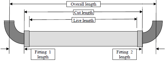
Type A – Assembly with one straight hose section and a single solid (non-swivel) fitting welded each end.
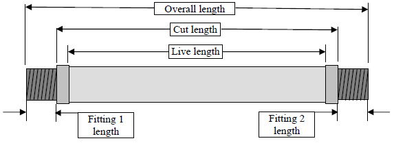
Where:
- Overall length (OAL) = The total length of the assembly
- Cut length = The length that the hose and braid are cut to before assembly fabrication
- Live length = The length of the hose between the inner edges of the braid collars. This is the portion of the hose which can actually move to take up assembly bending and vibration in service.
- Fitting 1 length = The total length of the fitting on assembly end 1
- Fitting 2 length = The total length of the fitting on assembly end 2
To calculate the hose cut length for a Type A assembly we need to:
1. Determine the Fitting 1 length.
2. Determine the Fitting 2 length and
3. Calculate Hose cut length = OAL – (Fitting 1 length + Fitting 2 length)
Example: OAL as ordered by customer = 24″
Fitting 1 length = 3″
Fitting 2 length = 2-1/2″
Hose cut length = 24 – (3″+ 2-1/2″) = 18-1/2″
Type B – An assembly with one straight hose section and a single solid (non-swivel) fitting welded each end and an additional threaded fitting (such as a pipe union or a threaded flange) threaded to one, or both, of the welded fittings.
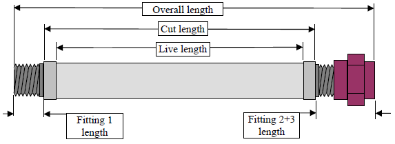
Where:
- Fitting 2+3 length = The total length of fitting 2 + fitting 3, tightly threaded together
To calculate the hose cut length for a Type B assembly we need to:
1. Determine the Fitting 1 length
2. Determine the Fitting 2 + 3 length by tightly threading the fittings together and measuring the total length
3. Calculate Hose cut length = OAL – (Fitting 1 length + Fitting 2+3 length)
Example: OAL as ordered by customer = 24″
Fitting 1 length = 3″
Fitting 2+3 length = 4-1/2″
Hose cut length = 24 – (3″+ 4-1/2″) = 16-1/2″
Type C – Type C – Assembly with one straight hose section and an elbow fitting on one or both ends.
Where:
- Fitting 1 length = The total length of the fitting on assembly end 1, measured from elbow end to the centerline of the fitting other end
- Fitting 2 length = The total length of the fitting on assembly end 2, measured from elbow end to the centerline of the fitting other end
To calculate the hose cut length for a Type C assembly we need to:
1. Determine the Fitting 1 length
2. Determine the Fitting 2 length
3. Calculate Hose cut length = OAL – (Fitting 1 length + Fitting 2 length)
Example: OAL as ordered by customer = 24″
Fitting 1 length = 3″
Fitting 2 length = 3″
Hose cut length = 24 – (3″+ 3″) = 18″
Type D – Type D – An assembly with one straight hose section and a swivel female fitting (such as a JIC) welded to one, or both, assembly ends.
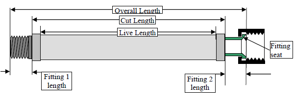
Where:
- Fitting 1 length = The total length of the fitting on assembly end 1
- Fitting 2 length = The total length of the fitting on assembly end 2
To calculate the hose cut length for a Type D assembly we need to:
1. Determine the Fitting 1 length
2. Determine the Fitting 2 length
3. Calculate Hose cut length = OAL – (Fitting 1 length + Fitting 2 length)
Example: OAL as ordered by customer = 24″
Fitting 1 length = 3″
Fitting 2 length = 3″
Hose cut length = 24 – (3″+ 3″) = 18″
We’ll take a look at how to calculate hose “cut length” for the Type E – assembly with two hose sections joined by an angled (45° or 90°) elbow in the next Engineering Bulletin.
If you have any questions or comments, please contact us.
To print, please click here.